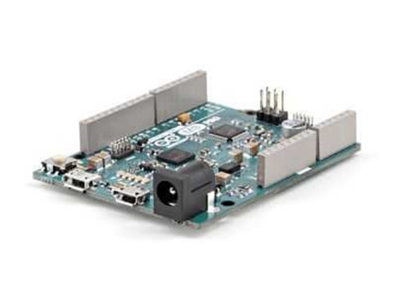

Original Arduino M0 PRO - Arduino Zero Pro
You can enter the maker's world by developing IoT, wearable technologies, high technology automation and many other applications which are limited by your imagination with new Arduino M0 Pro board.
Arduino M0 Pro is the simpler but more powerful version of Arduino Uno. This Board is powered by an 32-bit ARM Cortex® M0 architecture SAMD212 MCU of Atmel. The Arduino family have gained a high power board with Arduino M0 Pro.
Arduino M0 Pro will give you new ideas by providing flexibility for your projects with its high power core. Arduino M0 Pro will be your most suitible tool for developing 32-bit applications. Atmel's integrated Embedded Debugger (EDBG) will provide a full-function debugger interface for you. Moreover, the EDBG can open a virtual COM port to you computer for bootloader and programming.
Technical Features:
- Microcontroller: ATSAMD21G18, 48 pins, LQFP
- Operating voltage: 3.3 V
- Digital I/O pins: 14, 12 PWM and UART
- Analog I/O pins: 6, 12-bit ADC channels
- Analog output pins:1 10-bit DAC
- DC current: 7 mA for each I/O pins
- Flash memory: 256 kB
- SRAM: 32 kB
- EEPROM: up to 16 kB
- Clock speed: 48 MHz
- Dimensions: 53 x 70 x 14 mm
- Weight: 224g
Power:
Arduino M0 Pro can be supplied via usb or an external voltage source. External voltage source would be an AC - DC adapter or a battery. When it is supplied with an external adapter or battery, using 2.1 mm width, center-positive, 6 - 15 V power supply is recommended.
The board chooses the power supplies respect to priorities:
1 - External voltage input.
2 - Usb debug connection on the board
3 - External usb device
When you supply your board via an external usb device, if the current draw from usb connector (500 mA) is not enough, an external power supply should be used.
Power pins on the board:
- Vin: When an external adapter is used, the voltage of the adapter is on this pin. You can supply the board by applying 7-20 V among this pin instead of the on-board power connector.
- 5 V: The 5 V pin on the board is directly connected to the output of the regulator. To supply the board directly from this pin is not recommended due to that this way will not activate the 3.3 V and 5 V regulators on the board.
- GND: Ground pins on the board.
- 3.3 V: 3.3 V out pin from the regulator. Max. current is 1 A.
- IOREF: Operating voltage for I/O pins, 3.3 V for Arduino M0.
Memory:
ATSAMD21D18 microcontroller has a 256 kB flash memory. (4 kB is used by bootloader.) The bootloader comes as written on the ROM memory of the microcontroller. The bootloader is protected by NVM fuse. ATSAMD21G18 has 32 kB SRAM memory.
Input / Output:
All of the 14 digital pins on the M0 Pro can be configured as output or input pins. The logic level for all of these pins is 3.3 V. These pins work with 7 mA input or output current. There is an internal 20-60 kΩ pull-up resistor for each pin on the board. Additionally, some of these pins have diffrent features too, listed below:
- Serial (UART: 0(RX) and 1(TX) pins are used for firmware serial communication of Arduino M0 Pro. Serial commands on Arduino Leonardo is used for virtual COM port communication. You may use Serial1 commands if you want to use RX and TX pins..
- PWM: Pins from 2 to 13 can provide 8-bit analog out using analogWrite() function. The PWM out resolution can be changed with analogWriteResolution() function command. Additinally, pin and pin 10 or pin 5 and pin can not be used as PWM out at the same time.
- SPI: Can be found on ICSP headers. Unlike ATmega328p based boards like Arduino UNO, digitals pins should not be used together with SPI pins. If you have a shield using SPI communication and if there is not headers on it for ICSP pins, your shield will not work with this board.
- I2C, 2 (SDA) pin and 3 (SCL) pin: These pins are used for I2C serial communication.
- LED: There is a LED connected to digital pin 13. When a logic-1 signal applied, the LED blinks.
- Analog Inputs: A0 - A5 and A6 - A11 (digital 4, 6, 8, 9, 10, and 12 pins) can be used to read 10-bit analog signals. As default, the referance range of analog inputs is between 0-5 V. This range can be changed by using AREF pin and analogReferance() function.
- AREF: The referance pin for analog input.
- DAC (Digital - to - Analog - Converter): The pin A0 can be used to get a real 10-bit analog out by analogWrite() function. You can use this pin for your sound projects with Audio library of Arduino.
- Reset: If logic-0 voltage level applied to this pin, the board resets itself.
Communication:
Arduino M0 Pro holds various units for communication with a computer, another Arduino, pad, mpbile phone or camera. There are 3 USARTs (3.3 V) and one UART for serial communication on the board.
The Programming Port is connected to the EDBG which provides a virtual serial COM port for the computer. An EDGB driver is needed on Windows systems to be seen by the computer. The EDBG is connected to the physical UART of SAMD21 mcu too. RX0 and TX1 pins allows you to program ATSAMD21 mcu from your computer. Arduino IDE, thanks to its serial monitor find in the computer software, provides to send and recieve text based information. RX and TX leds on the board blink while the board is communicating via USB.
Native Port is wired to SAMD2 directly and allows serial communication via usb. By this way you can communicate with the serial monitor or the other applicaitons. Thanks to these features, M0 Pro can be introduced to computer as not only virtual COM port but also as peripherals such as smart phone, console and mouse too.
SAMD21 supports TWI and SPI serial communication protocols too.
Programming:
Arduino M0 Pro can be programmed by using Arduino Software package. Unlike the other Arduino boards, Arduino M0 Pro needs its flash memory erased before its programmed. There is a specific part in the ROM memory of SAMD21 to control programming.
Both of the usb ports can be used to program the board.
Programming Port (The one near DC power supply connector ): To use this port you should choose "Arduino M0 Pro (Programming Port)" in Arduino IDE. The SAMD21 MCU will be exposed to "hard erase". This mehtod gives better results then "soft erase" done by Native Port. Programming Port is the recommended port for programming. Even the chip is hard erased, it is possible to program and erasing with this port.
Native Port (The one near the reset button): To use this port you should choose "Arduino M0 Pro (Programming Port)" in Arduino IDE. Programming with this port makes "soft erase" to the chip and resets the mcu and the bootloarder starts again.
Usb high current protection:
Arduino M0 Pro board has restarable high current protectors. Even if your computer has its own protectors for its USB ports, the protectors on the board is adjusted to reject more than 500mA. If this amount of current is reached, protectors will keep open - circuit the connection untill the short - circuit disappears.