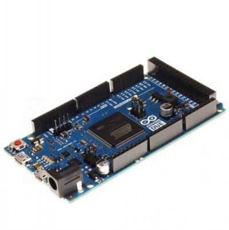
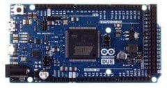
Original Arduino DUE R3
Warning: Unlike other Arduino boards, Arduino Due's operation voltage is 3.3 V. Input and outpur pins work on 3.3 V. Applying high voltages like 5 V might harm the board.
This board is compatible with just 3.3 V shields.
Advantages of an ARM Core:
There is a 32-bit Arm core on Arduino Due. The most important advantages are:
- A 32-bit processor allows you to process 4-byte data in a processor hour.
- The processor works with 84 Mhz clock speed
- 96 kB SRAM
- 512 kB flash memory
- DMA controller, helps memory processes.
Features:
- Microcontroller: AT91SAM3X8E
- Operating voltage: 3.3 V
- Supply voltage (recommended): 7-12 V
- Supply voltage (limits): 6-16 V
- Number of digital I/O pins: 54
- Number of PWM pins: 12
- Number of analog input pins: 12
- Max DC current for each I/O pins: 130 mA
- Analog out: 2 (DAC)
- DC current for 3.3 V out: 800 mA
- Flash memory: 512 kB (SAM3x8E)
- SRAM: 96 kB (SAM3X8)
- Clock speed: 84 MHz
- Length: 101.52 mm
- Width: 53.3 mm
- Weight: 36 gr
Power:
Arduino Due can be supplied via usb or an external voltage source. External voltage source would be an AC - DC adapter or a battery. When it is supplied with an external adapter or battery, using 2.1 mm width, center-positive, 7-16 V power supply is recommended. Moreover, the connectors of the power socket on the board, Vin and GND pins are short circuited in beckend. The battery can be connected to the board via GND and Vin pins.
It is not necessary to be connected to usb port during whole the operation. The board can be energized with only an adapter or a battery too, by this way, the board can work independently from the computer.
6 - 20 V can be used as an external supply but these are the limits for Due. Recommanded voltage supply for this board is between 7 - 20 V. Becouse the regulator on the board might not work stabile for the voltages below 7V. Likewise, it can be over - warmed for the voltages above 12 V.
Operating voltage of the Arduino Due's microcontroller is 5 V. The voltage supplies the board via Vin pin or the power socket on 7 to 12, V then this voltage is regulated and distributed to the board by the regulator.
Power pins are like that:
- Vin: When an external adapter is used, the voltage of the adapter is on this pin. You can supply the board by applying 7-20 V among this pin instead of the on-board power connector.
- 5 V: The 5 V pin on the board is directly connected to the output of the regulator. To supply the board directly from this pin is not recommended due to that this way will not activate the 3.3 V and 5 V regulators on the board.
- GND: Ground pins on the board.
- 3.3 V: 3.3 V out pin from the regulator. Max. current is 50 mA.
Memory:
SAM3X8E has an 512 kB flash memory and 96 kB SRAM.
Flash memory of the SAM3X8E can be erased by erase button. This will clear just the arduino code you uploaded, the bootloader software will not be changed. It is enough yo activate this button by pushing it for a few seconds.
Input / Output:
All of the 54 digital pins on the Due can be configured as output or input pins. It has 12 analog input pins too. The logic level for all of these pins is 3.3 V. Output currents vary on the pin used (For input: 6 - 9 mA, for output: 3 - 15 mA). Additionally, some of these pins have diffrent features too, listed below:
- Serial Communication, Serial: 0 (RX) and 1 (TX), Serial1: 19 (RX) and 18 (TX), Serial2: 17 (RX) and 16 (TX), Serial3: 15 (RX) and 14 (TX) : These pins are used to recieve (RX) and Transmit (Tx) TTL data. These pins are directly connected to Atmega16u2 usb - serial converter chip on the Due board, that means when the board is getting programmed or while the Due and computer is communicating these pins are in use. Becouse of this situation it is recommended not to use these pins when the other pins are free.
- PWM, 1-13: These pins can be used as 8-bit PWM outs. You can change the resolution with analogWriteResolution() function.
- SPI, ICSP Headers: These pins are used for SPI communication. There are an 3x2 header SPI port on the board. However this port is not used to program SAM3X processor like the other Arduino boards. There are some further information about these pins on Extended SPI methods for Due Pag.
- CAN, CANRX, CANTX : These are CAN communication protocol pins but this protocol is not supported by the Arduino API.
- Analog, A0 - A11: Due holds 12 12-bit analog input pins. These pins are set 10-bit to be compatible with the other Arduino boards.These pins may be set 12-bit with analogReadResolution() function. These pins are also able to be set as outputs. You can change the level with AREF pin. If you want to use this feature, you need to remove BR1 pin on the board.
- DAC1 and DAC2:
Communication:
Programming:
You can program Arduino Due via Arduino Computer Software (Arduino IDE). For details please have a look: referance and basic functions.
Uploading code to SAM3X is a little diffrent from the other Arduino boards. Becuose you should erase first the code already uploaded and stays in the flash memory.
Usb high current protection:
Arduino Due board has restarable high current protectors. Even if your computer has its own protectors for its USB ports, the protectors on the board is adjusted to reject more than 500mA. If this amount of current is reached, protectors will keep open - circuit the connection untill the short - circuit disappears.

