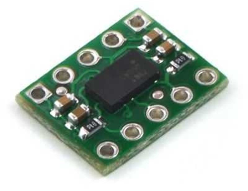
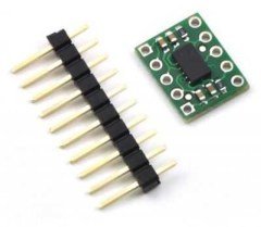
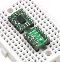
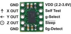
MMA7341LC XYZ-axis accelerometer, a great low-g sensor with analog voltage outputs, adjustable sensitivity (±3 g or ±9 g), and a 0g-detect digital output that signals when the board is in free-fall. The board operates from 2.2 to 3.6 V. This breakout board has the form factor of a 10-pin DIP package, which makes it easy to use with standard solderless breadboards and 0.1″ perfboards, and the unit is smaller than competing products, all at a lower price.
- Output Format: Analog Voltage
- Minimum Operating Voltage: 2.2 V
- Maximum Operating Voltage: 3.6 V
- Sensitivity Range: ± 3 g or ± 9 gr
- Operating Current: 0.5 mA
- Sleep Mode Current Draw: <3 uA
- Dimensions: 12.7 x 10.2 mm
- Weight: 0.35 g
Using the sensor:
The board is powered by supplying 2.2 V to 3.6 V on the VDD pin. Note that this part does not have 5V-tolerant pins, so external components (such as voltage dividers) are required when interfacing the board’s g-Select, Self Test, and Sleep pins with 5V systems. Connections to these pins are optional; the board will work with these pins disconnected as long as the sleep pin is driven high with an on-board solder bridge as described below.
The sleep pin, Sleep, is internally pulled low, which puts the board into low-power sleep mode by default. You must drive this pin high to use the board. This can be accomplished with a microcontroller I/O line if you want selective control of sleep mode, or you can make a solder bridge across the SMT jumper pads labeled “ON” on the silkscreen side of the board to connect the sleep pin to VDD and enable the board by default.
The accelerometer X, Y, and Z outputs are three separate analog voltages centered at VDD/2. Positive accelerations along an axis increase that axis’s output voltage above VDD/2 and negative accelerations decrease the output voltage below VDD/2. The outputs will always be within the range of 0 to VDD.
The sensitivity selection pin, g-Select, is internally pulled low, which selects for a default sensitivity of ±1.5g (800 mV/g) on the MMA7361LC carrier and ±3g (440 mV/g) on the MMA7341LC carrier. Driving the pin high selects for a sensitivity of ±6g (206 mV/g) on the MMA7361LC carrier and ±9g (118 mV/g) on the MMA7341LC carrier.
The 0g-Detect pin outputs high when all three axes simultaneously detect 0g, which happens when the board is in free-fall. This pin is only documented in the datasheet of the more sensitive MMA7361LC IC (the MMA7341LC datasheet labels this pin as “NC”), but we have found that it works on the MMA7341LC at its default ±3g sensitivity. This output does not work at the ±9g sensitivity setting.
The Self Test pin is pulled low on the board and can be left disconnected.

