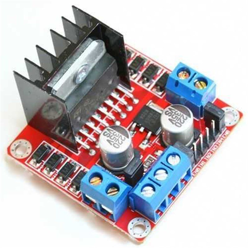
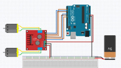
L298 Dual H-Bridge DC Motor Controller
3,00 USD
This motor driver board is designed for motors which operation voltages are up to 24V. Driver has two channel and delivers 2A current per channel. L298N motor driver IC is used on board. Board can be used at various motor control implementations like sumo, mini sumo and line follower robots.

The L298 Dual H-Bridge DC Motor Controller will allow you to easily and independently control two motors of up to 2A each in both directions.It is ideal for robotic applications and well suited for connectionto a microcontroller requiring just a couple of control lines per motor.It can also be interfaced with simple manual switches, TTL logic gates,relays, etc.
Features :
- Board can control two motors seperately.
- Deliver 2A current per channel.
- Internal regulator is available.
- High temperature and shortcut protection is avaliable.
- LEds, which light according motor direction, are available.
- Internal cooler is available.
- Current sense pins are available as emitted.
- Four screw holes are available at four sides of board.
Pin Mapping:
- ENA: Pin is used for left motor activation
- IN1: Left motor 1. input
- IN2: Left motor 2. input
- IN3: Right motor 1. input
- IN4: Right motor 2. input
- ENB: Pins is used for motor channel activation
- MotorA: Left motor output
- MotorB: Right motor output
- VCC: Supply voltage input(4.8V-24V)
- GND: Ground connection
- 5V: 5V output
- Jumper plugged pins are available on the board. These pins can be used for optional usages and activate different properties.
- CSA: Current output of A motor driver. With a jumper, current draw value can be read as anlog voltage value.
- CSB: Current output of B motor driver. With a jumper, current draw value can be read as anlog voltage value.
- V1 is a jumper plugged to the pull-up resistor which sends IN1 input to 5V directly. Through this, as you don't plug it to ground, pin voltage level stays as 5V.
- V1 is a jumper plugged to the pull-up resistor which sends IN2 input to 5V directly. Through this, as you don't plug it to ground, pin voltage level stays as 5V.
- V1 is a jumper plugged to the pull-up resistor which sends IN3 input to 5V directly. Through this, as you don't plug it to ground, pin voltage level stays as 5V.
- V1 is a jumper plugged to the pull-up resistor which sends IN4 input to 5V directly. Through this, as you don't plug it to ground, pin voltage level stays as 5V.
- 5V-EN jumper activates or deactivates 7805 line. If it's plugged 5v output of board becomes active . If it's unplugged this line becomes deactive.

Be the first to comment on this product!

