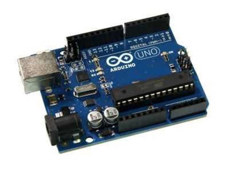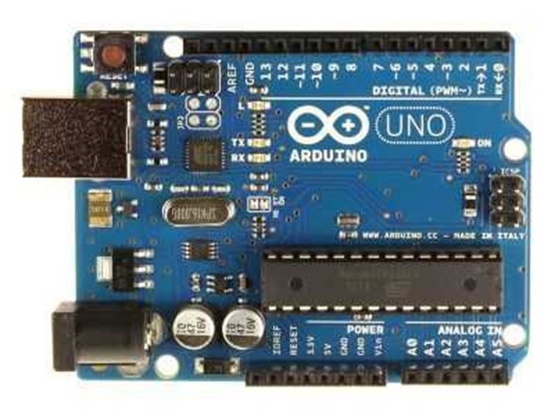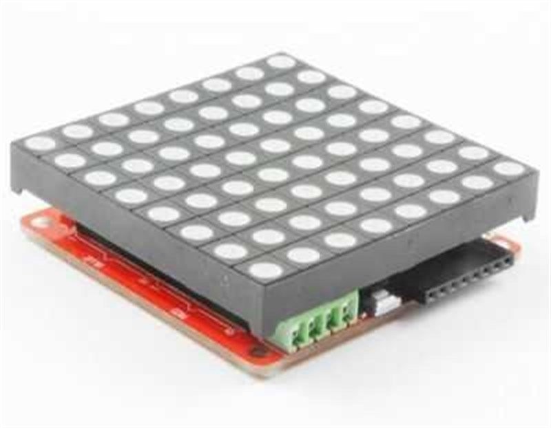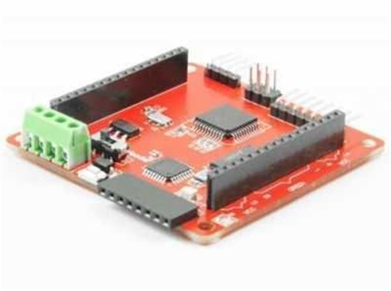
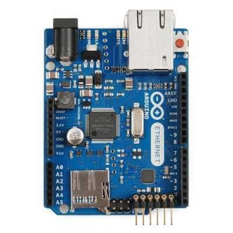
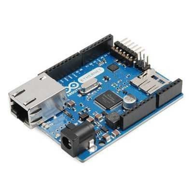
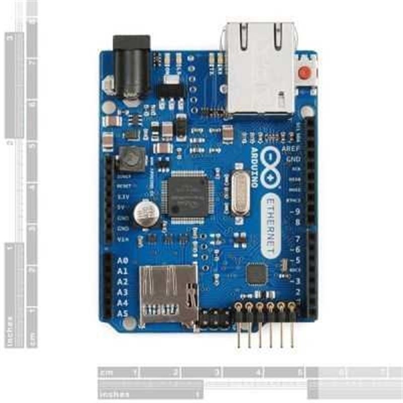
Original Arduino Ethernet w/o PoE R3 (New Version)
Note: Pin 10 (Ethernet SS), pin (Ethernet and SD MOSI), pin 12 (Ethernet and SD MISO), pin 13 (Ethernet and SD SCK) and pin 4 (SD SS) are reserved for ethernet and SD card, these pins should not be used for any other operations. Becouse of this reason, number of digital pins goes down to 8 and number of PWMs to 4.
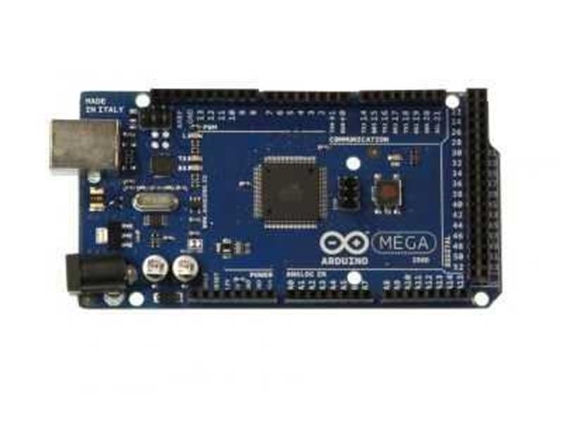
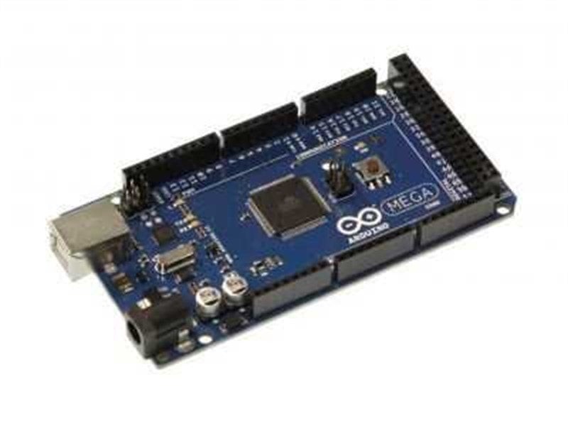
Unlike the other models of Arduino, there is not a usb to serial converter chip on this board but Arduino Ethernet supports Ethernet interface.
The Arduino Ethernet with the Poe modul also exsists.
It is possible to store intformation to use in network applications and use the SD library with the internal micro SD card socket. The SS pin for Wiznet is pin 10 and for SD card is 4.
Features:
- Microcontroller: ATmega328
- Operating voltage: 5 V
- Supply voltage (recommended): 7-12 V
- Supply voltage (limits): 6-20 V
- Input voltage (POE): 36 - 57 V
- Number of digital I/O pins: 14
- Number of PWM pins: 6
- Pins in use: 10 - 13 SPI, 4 SD SS, 2 Wz5100 interrupt
- Number of analog input pins: 6
- Max DC current for each I/O pins: 40 mA
- DC current for 3.3 V out: 50 mA
- Flash memory: 32 kB (ATmega328, 0.5 kB is used by bootloader)
- SRAM: 2 kB (ATmega328)
- EEPROM: 1kB (ATmega328)
- Clock speed: 16 MHz
- W5100 TCP/IP Embedded Ethernet controller
- Power Over Ethernet
- Micro SD card socket
- Length: 68.6 mm
- Width: 53.4 mm
Power:
Arduino Ethernet can be supplied via usb or an external voltage source. External voltage source would be an AC - DC adapter or a battery. When it is supplied with an external adapter or battery, using 2.1 mm width, center-positive, 7-20 V power supply is recommended. Moreover, the connectors of the power socket on the board, Vin and GND pins are short circuited in beckend. The battery can be connected to the board via GND and Vin pins.
It is not necessary to be connected to usb port during whole the operation. The board can be energized with only an adapter or a battery too, by this way, the board can work independently from the computer.
6 - 20 V can be used as an external supply but these are the limits for Arduino Ethernet. Recommanded voltage supply for this board is between 7 - 20 V. Becouse the regulator on the board might not work stabile for the voltages below 7V. Likewise, it can be over - warmed for the voltages above 12 V.
Operating voltage of the Arduino Ethernet's microcontroller is 5 V. The voltage supplies the board via Vin pin or the power socket on 7 to 12, V then this voltage is regulated and distributed to the board by the regulator.
Power pins are like that:
- Vin: When an external adapter is used, the voltage of the adapter is on this pin. You can supply the board by applying 7-20 V among this pin instead of the on-board power connector.
- 5 V: The 5 V pin on the board is directly connected to the output of the regulator. If the board is supplied by usb (5 V), 5 V of the usb directly comes this pin. If the board is supplied by an external power supply or from Vin pin then the voltage of the 5 v pin comes from output of the regulator.
- 3.3 V: 3.3 V out pin from the regulator. Max. current is 50 mA.
- AREF: It is possible to change the referance voltage of the board.
- GND: Ground pins on the board.
Memory:
Atmega328 has an 32 kB flash memory (0.5 kB of this is used by the bootloader), 2 kB SRAM and 1 kB EEPROM.
Input and Output:
All of the 14 digital pins on the Arduino Ethernet board can be configured both as an input or an output. There are 6 analog input pins on the board too. All of these analog pins can be configured as digital input or output. In total there are 20 digital input - output pins on the board. Logic level of these pins are all 5 V. All of these pins are able to provide an output current up to 40 mA. Additionally, some of these pins have diffrent features too, listed below:
- Serial Communication, 0 (RX) and 1 (TX): These pins are used to recieve (RX) and Transmit (Tx) TTL data. These pins are directly connected to Atmega16u2 usb - serial converter chip on the Arduino Ethernet board, that means when the board is getting programmed or while the Arduino Ethernet and computer is communicating these pins are in use. Becouse of this situation it is recommended not to use these pins when the other pins are free.
- External Interrupts: By using the pins 2 (Interrupt 0), 3 (interrupt 1) you may activate interrupts respect to logic-1 and logic-0 levels and/or rising edge or falling edge. You can find the details on the attachInterrupt() function page.
- PWM: Pins 3, 5, 6, 9, 10, 11 and 13 can provide 8-bit analog out using analogWrite() function.
- SPI: 10 (SS), 11 (MOSI), 12 (MISO), 13 (SCK) pins are used for SPI communication.
- Analog: A0 - A5; Ethernet board has 6 10-bit analog input pins. These pin may be used also as digital input or output. As default, the referance range of analog inputs is between 0-5 V. This range can be changed by using AREF pin and analogReferance() function.
- I2C, A4 (SDA) pin and A5 (SCL) pin: These pins are used for I2C serial communication.
- AREF: The referance pin for analog input.
- Reset: If logic-0 voltage level applied to this pin, the board resets itself.
You may view the pin mapping page from this link.
Communication:
There are several options for Arduino Ethernet to communicate with another arduino or microcontroller. Atmega328 provides UART TTL (5V) Serial communication via its 0 (RX) and 1 (TX) pins. Atmega328 connects to a computer by opening a virtual serial COM port and allows the serial communication. Arduino IDE, thanks to its serial monitor find in the computer software, provides to send and recieve text based information. RX and TX leds on the board blink while the board is communicating via USB.
There is a phsycally serial port on the Ethernet board but this number can be increased with the SoftwareSerial library as software.
Atmega328 provides I2C and SPI ports too. Wire library if to use I2C and SPI library is for SPI communication.
Programming:
There is not an usb to serial converter chip on the board so to program the board you may choose usb to serial converters. To wire an external usb-serial converter, it is possible to use 6 - pin programming headers on the board.
The board can be programmed by using ICSP headers via ISP programmer instead of bootloader software (Referance).
All the applications developed on Ethernet Shield will work on the Arduino Ethernet too. It is not needed to chane anything.
Note: The Arduino Ethernet with the Poe modul also exsists.