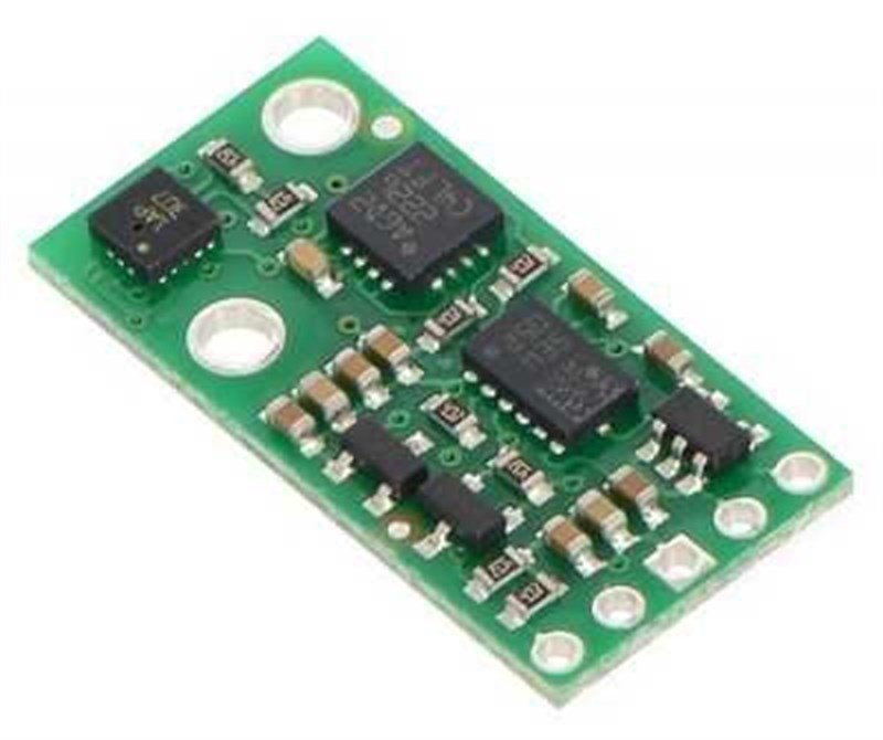
AltIMU-10 v5 Gyro, Accelerometer, Compass, and Altimeter (LSM6DS33, LIS3MDL, and LPS25H Carrier)
Compared to the previous AltIMU-10 v4, the v5 version uses newer MEMS sensors that provide some increases in accuracy (lower noise and zero-rate offsets). The AltIMU-10 v5 is pin-compatible with the AltIMU-10 v4, but because it uses different sensor chips, software written for older IMU versions will need to be changed to work with the v5.
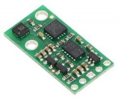
The AltIMU-10 v5 is also pin-compatible with the MinIMU-9 v5 and offers the same functionality augmented by a digital barometer that can be used to obtain pressure and altitude measurements. It includes a second mounting hole and is only 0.2″ longer than the MinIMU-9 v5. Any code written for the MinIMU-9 v5 should also work with the AltIMU-10 v5.
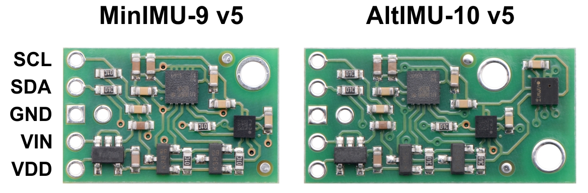 |
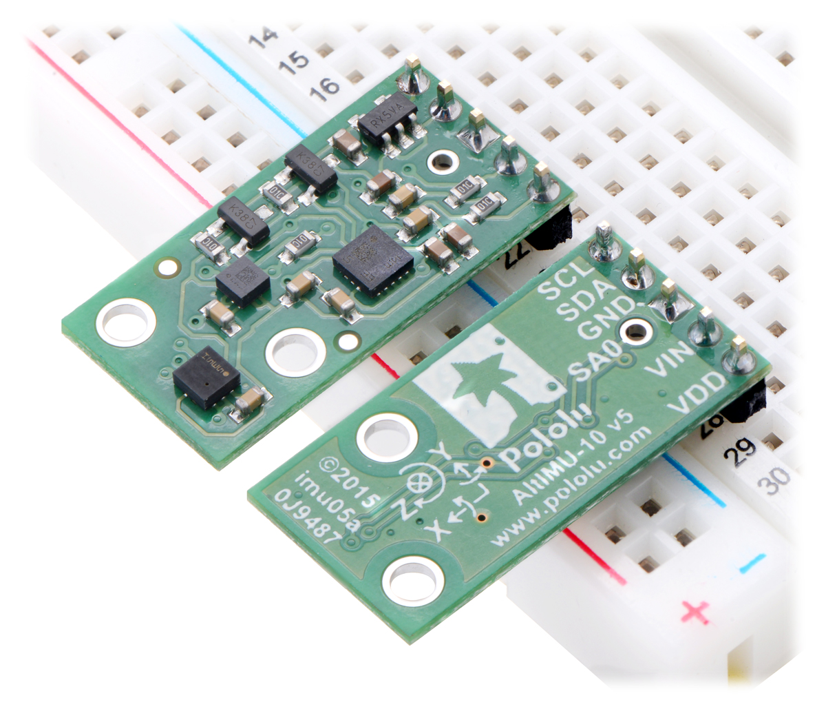
Side-by-side comparison of the MinIMU-9 v5 with the AltIMU-10 v5. |
|---|
The LSM6DS33, LIS3MDL, and LPS25H have many configurable options, including dynamically selectable sensitivities for the gyro, accelerometer, and magnetometer and selectable resolutions for the barometer. Each sensor also has a choice of output data rates. The three ICs can be accessed through a shared I²C/TWI interface, allowing the sensors to be addressed individually via a single clock line and a single data line. Additionally, a slave address configuration pin allows users to change the sensors’ I²C addresses and have two AltIMUs connected on the same I²C bus. (For additional information, see the I²C Communication section below.)
The nine independent rotation, acceleration, and magnetic readings provide all the data needed to make an attitude and heading reference system (AHRS), and readings from the absolute pressure sensor can be easily converted to altitudes, giving you a total of ten independent measurements (sometimes called 10DOF). With an appropriate algorithm, a microcontroller or computer can use the data to calculate the orientation and height of the AltIMU board. The gyro can be used to very accurately track rotation on a short timescale, while the accelerometer and compass can help compensate for gyro drift over time by providing an absolute frame of reference. The respective axes of the two chips are aligned on the board to facilitate these sensor fusion calculations. (For an example of such a system using an Arduino, see the picture below and the Sample Code section at the bottom of this page.)
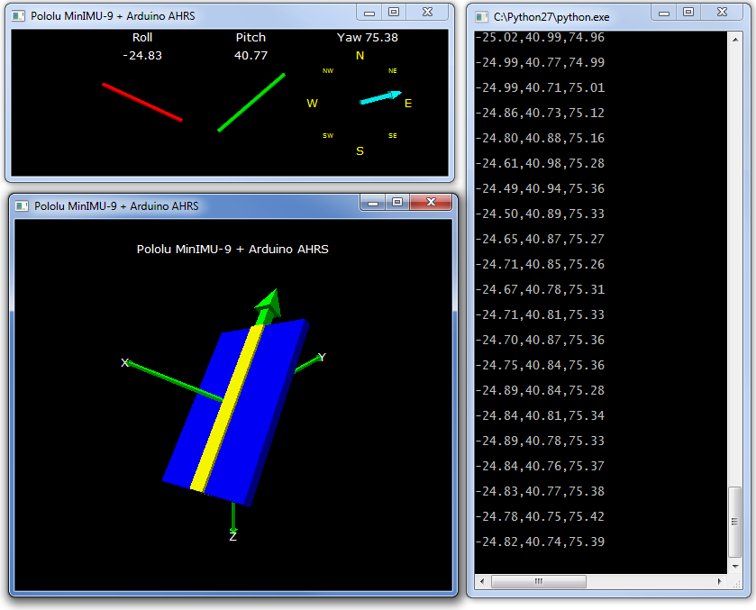 |
Visualization of AHRS orientation calculated from MinIMU-9 readings. |
|---|
The carrier board includes a low-dropout linear voltage regulator that provides the 3.3 V required by the LSM6DS33, LIS3MDL, and LPS25H, allowing the module to be powered from a single 2.5 V to 5.5 V supply. The regulator output is available on the VDD pin and can supply almost 150 mA to external devices. The breakout board also includes a circuit that shifts the I²C clock and data lines to the same logic voltage level as the supplied VIN, making it simple to interface the board with 5 V systems. The board’s 0.1″ pin spacing makes it easy to use with standard solderless breadboards and 0.1″ perfboards.
Specifications
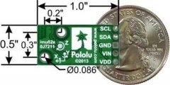
- Dimensions: 1.0″ × 0.5″ × 0.1″ (25 mm × 13 mm × 3 mm)
- Weight without header pins: 0.8 g (0.03 oz)
- Operating voltage: 2.5 V to 5.5 V
- Supply current: 5 mA
- Output format (I²C):
- Gyro: one 16-bit reading per axis
- Accelerometer: one 16-bit reading per axis
- Magnetometer: one 16-bit reading per axis
- Barometer: 24-bit pressure reading (4096 LSb/mbar)
- Sensitivity range:
- Gyro: ±125, ±245, ±500, ±1000, or ±2000°/s
- Accelerometer: ±2, ±4, ±8, or ±16 g
- Magnetometer: ±4, ±8, ±12, or ±16 gauss
- Barometer: 260 mbar to 1260 mbar (26 kPa to 126 kPa)
Included Components
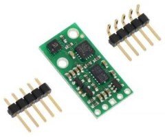
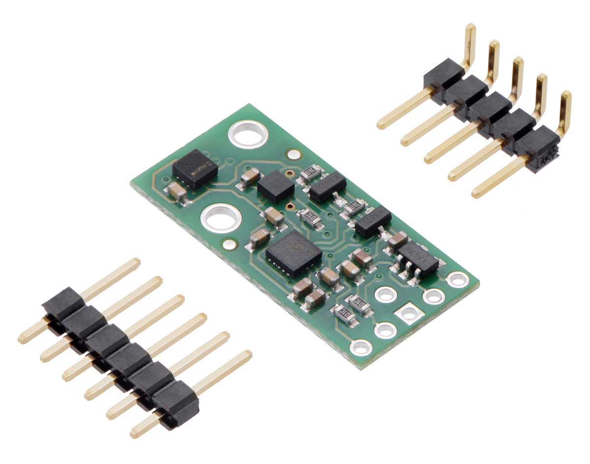
A 1×6 strip of 0.1″ header pins and a 1×5 strip of 0.1″ right-angle header pins are included, as shown in the picture below. You can solder the header strip of your choice to the board for use with custom cables or solderless breadboards or solder wires directly to the board itself for more compact installations. The board features two mounting holes that work with #2 or M2 screws (not included).
 |
Using the AltIMU-10 v5
Connections
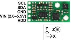
A minimum of four connections is necessary to use the AltIMU-10 v5: VIN, GND, SCL, and SDA. VIN should be connected to a 2.5 V to 5.5 V source, GND to 0 volts, and SCL and SDA should be connected to an I²C bus operating at the same logic level as VIN. (Alternatively, if you are using the board with a 3.3 V system, you can leave VIN disconnected and bypass the built-in regulator by connecting 3.3 V directly to VDD.)
|
|

Pinout
| PIN | Description |
|---|---|
| SCL | Level-shifted I²C clock line: HIGH is VIN, LOW is 0 V |
| SDA | Level-shifted I²C data line: HIGH is VIN, LOW is 0 V |
| GND | The ground (0 V) connection for your power supply. Your I²C control source must also share a common ground with this board. |
| VIN | This is the main 2.5 V to 5.5 V power supply connection. The SCL and SDA level shifters pull the I²C bus high bits up to this level. |
| VDD | 3.3 V regulator output or low-voltage logic power supply, depending on VIN. When VIN is supplied and greater than 3.3 V, VDD is a regulated 3.3 V output that can supply up to approximately 150 mA to external components. Alternatively, when interfacing with a 2.5 V to 3.3 V system, VIN can be left disconnected and power can be supplied directly to VDD. Never supply voltage to VDD when VIN is connected, and never supply more than 3.6 V to VDD. |
| SA0 | 3.3V-logic-level input to determine I²C slave addresses of the three ICs (see below). It is pulled high by default through 10 kΩ resistor. This pin is not level-shifted and is not 5V-tolerant. |